Now that you have configured analog and digital input points and digital output points, you can configure a Mimic to show their values. The Mimic will provide a graphical display that contains an overview of the points’ values.
To configure a Mimic to contain dynamic data for the points:
- Display the Database Bar (see Display an Explorer Bar).
- In the Database Bar, expand the 'Site' Group, then double-click on the 'Default' Mimic to display its editor.
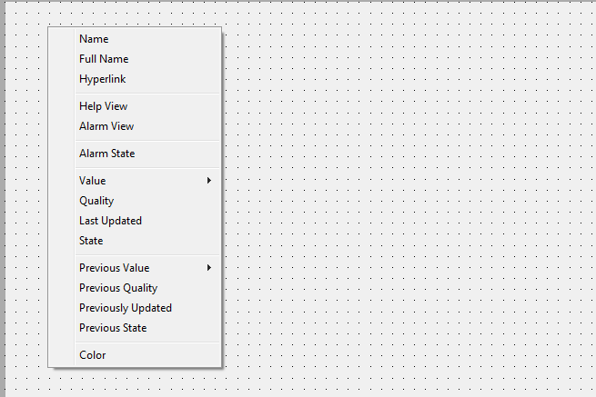
- In the Database Bar, select the 'AI 1' point and drag it onto the display area of the Default Mimic. Release the mouse button to display a context sensitive menu.
- Select the Name option from the context sensitive menu.

- This adds a text box to the Mimic, and the text box is automatically configured to be animated by the name property of the 'AI 1' point. So if the name property of the 'AI 1' point changes, the change will be shown on the Mimic automatically—there is no need to update the name value on the Mimic manually.

- Repeat steps 3 and 4, only this time select the Value>Formatted Value options. This adds a text box that is animated by the point’s CurrentValueFormatted property (as well as its Foreground, Background and Blink properties, which affect the appearance of the text in the text box).

- Repeat steps 3 and 4, only this time select the Value>Vertical Bar>Up options. This adds a vertical size bar that is animated automatically so that the size of the bar changes according to the value of the analog point.

- Repeat steps 3, 4 and 5 for the ‘AI 2’ point.
- For each of the digital points, add a Name text box and a State text box. To add a State text box, drag the point onto the Mimic, then select State from the menu.
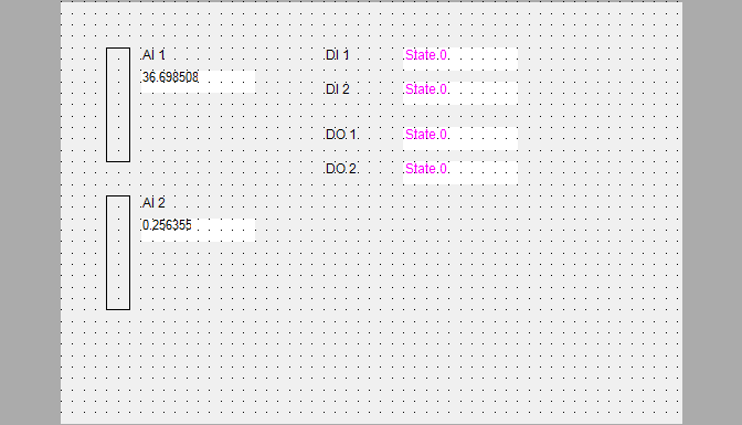
- Organize your Mimic objects so that your Mimic looks like this:

- Save the Mimic.
- Deselect the Design Mode button
 on the Quick Access Toolbar. This will display the Mimic in Run mode.
When you display a Mimic in Run mode, the Mimic’s configuration features become unavailable and the Mimic displays its dynamic data. Usually, operators will work with Mimics in Run mode.
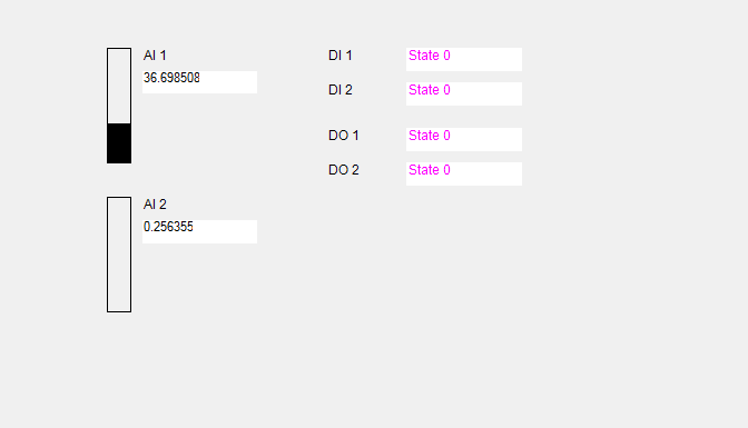
When you switch a Mimic from Design Mode to Run mode, the grid is turned off automatically, and so the grid dots are no longer visible. This is because grid lines are designed to help align objects during configuration and so are not required during operation.
You will also see that the animated size bars are now sized according to the analog input from your SCADAPack Modbus controller. Many animations are only visible when a Mimic is displayed in Run Mode.

Now you have a Mimic that displays live, 'dynamic' I/O. But the Mimic does more than just display data—it provides access to other displays and controls, as you will see in the next section: Display a Historic Trend for the 'AI 1' Analog Input Point.
Further Information
Displaying Data on a Mimic: see Animations.
Considerations when Creating and Configuring a Mimic: see Designing a Mimic.